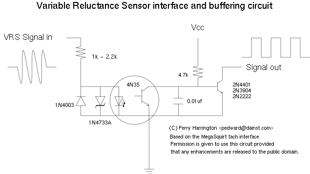
Here is another VRS interface circuit that works at lower input speeds/voltages. Additionally you many want to look at the applications section of the LM324 datasheet, it has a couple of very good Zero Crossing detector circuits, but they are more sensitive to noise.
The circuit below is based on a circuit I saw in the MegaSquirt schematics. That application used a 4N25 to buffer a tach signal.
The circuit below has been tested with a Ford VSS VRS sensor. The Ford sensor is an 8 pulse per revolution VRS sensor. The sensor outputs from 0.2 to 9 volts peak to peak AC. The zener diode in the circuit below truncates the maximum voltage at 5.1 volts, with the in circuit measured voltage of 1.5 volts. The 1 to 2.2k resistor is a current limiting resistor. It is intended to limit the current below 30ma. Depending on your application (max VRS voltage) use the correct resistor. For wide compatibility use 2.2k, as some sensors reach 50 volts. The 4.7k pullup isn't a super critical value, but I found that it makes a clean output pulse through the transistor. Optionally you can put another 4.7k pullup on the output of the transistor if your sink does not have an internal pullup. The circuit is sensitive from 0.5v p-p input voltage. This corresponds to 22 Hz with the Ford sensors. Below 0.5 volts the interface does not register pulses. If you look at a VRS, below 0.5 volts the signal is very non-uniform and is unsuitable. With a 50% input duty cycle the output signal of the circuit goes high at 20% of the positive going input pulse and goes low at 80% of the positive going pulse. Eg, if your positive going input pulse is 15ms, the ouput pulse is 6ms. This was observed on an oscilloscope.
