DAI Datalogging software
| The DAI Datalogging software shown below is in development. The completed software will be released under the GPL license with the source code freely available. The software is written in C++ and uses the Trolltech QT interface. This allows the software to be cross platform and is supported on the Sharp Zaurus PDA, Windows, and Linux. |
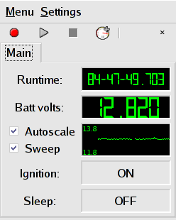
Main window as it would appear on the Sharp Zaurus PDA |
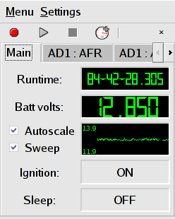
Program with multiple tabs open at one time. |
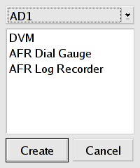
New gauge dialog (when you select a different input, it shows you the gauges available for that input) |
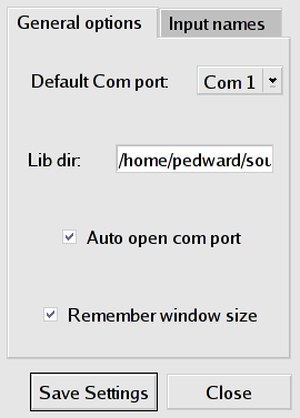
Configuration window, general configuration options. You can select the default Com port and whether you want to automatically open it every time you start the program. |
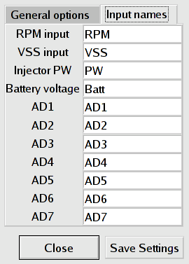
Configuration window, you can name the inputs. Everywhere in the program uses the custom input names. This is handy so that instead of referring to your Coolant sensor as "AD5", you would name it ECT or some such. |
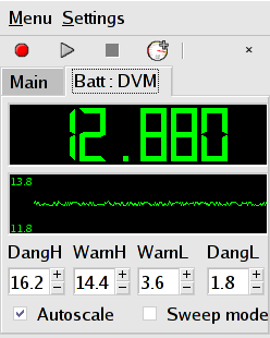
Here is the DVM (Digital Volt Meter) tab. It displays the voltage in LCD format as well as offering a chart recorder. The colorized limits are adjustable via spin boxes. |
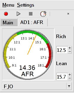
Air Fuel Ratio gauge. On the right are the spin boxes for setting the AFR values for the high and low AFR colors. On the bottom is a drop-down list box of supported O2 sensors. Shown is the FJO wideband sensor profile. DIY-WB, and 3 generic O2 sensor profiles are also supported. |
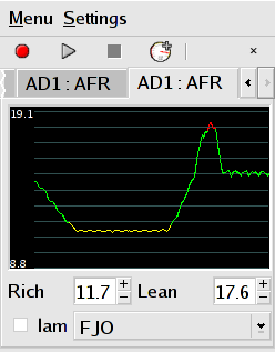
Here's a view of the AFR Log Chart Recorder tab. It converts the voltage input into an AFR value for the log recorder. You can also use the DVM tab to view the raw voltage in recorder format as well. |

This is the Tachometer gauge. You can set the Max RPM, Redline, and Warning zone values using the spin boxes. The Number of cylinders and cycles is set in the car configuration. |
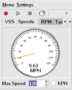
Here you can see the Speedometer gauge. It uses the VSS input to derive speed. The Pulses Per Mile of the VSS sensor is set in the car configuration dialog. You can select between MPH and KPH on the fly, and it give sub integer speed precision. You may also scale the speedometer by adjusting the Max Speed value. |
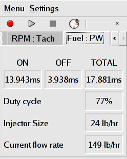
This is the Fuel injector pulsewidth and duty cycle tab. This shows you the injector on time, off time, and duty cycle. It displays the instantaneous fuel consumption as well as your configured injector size. The units change depending on the selection in the Car configuration dialog. |

Here is the Thermistor Temperature tab. You can interactively adjust the bias resistor value as well as view the measured resistance of the sensor. When you select different sensors, the minimum and maximum values are updated to reflect the new sensor. |
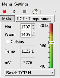
This is the Thermocouple/Non-Contact Infared Temperature tab. You can use it with any sensor that outputs a voltage. The output of the sensor is displayed in the native millivolt scale. Like the tab above, the scales are updated to reflect the limits of the sensor. Sensors with an output between 0 and 5 volts can be measured. |
||