|
This page is intended for people who want to learn about the Ford EDIS
(Electronic Distributorless Ignition System). The pinouts
and diagrams are taken from How to Understand, Service and Modify Ford
Electronic Fuel Injection & Electronic Engine Control by Charles
Probst, the technical information on the SAW and inner workings of the EDIS
module are taken from Ford Patent 4,922,874.
Introduction The Ford EDIS system is an enhanced version of the DIS ignition system. The major difference is that the DIS system requires a CID (Cylinder IDentification; cam phase) sensor in addition to the crank driven toothed wheel. The EDIS system only requires a 36-1 toothed wheel and VRS (Variable Reluctance Sensor) crank sensor. The EDIS system is comprised of an EDIS module, crank wheel, crank sensor, and coilpack(s). This system is completely standalone and will properly ignite 4, 6, and 8 cylinder engines using the wasted spark method. The system relies on the ECU (Electronic Control Unit) to control spark timing, but will function if no ECU is connected. Without an ECU the EDIS system will fire the ignition at 10 degrees BTDC (Before Top Dead Center). The spark advance is controlled by the SAWPW line on the EDIS module. The SAW (Spark Angle Word) is analguous to the SPOUT (Spark OUT) line on Ford TFI-IV systems. The interface is different though. Technical Background Inside the EDIS module is a microprocessor, VR sensor input, and coil driver transistors. The VR sensor drives an input detector which fires on the falling zero crossing of the signal at -300mv. The module then uses this information to calculate the current crank position and speed. When the EDIS module determines the spark should be ignited, it fires the appropriate coil. The EMF flyback from the coil then triggers the IDM of the EDIS module and causes it to emit a tach pulse on the IDM pin. The first thing the EDIS module does is sync up to the missing tooth of the wheel. The EDIS module keeps an internal counter of teeth, if for some reason the counter loses sync with the wheel, the module will attempt to resync. Each EDIS module is hard programmed for the number of cylinders in the intended application. By knowing the number of cylinders, it knows how many teeth are between each cylinder on the crank wheel. When the number of teeth required passes the VR sensor, the EDIS module emits the PIP signal to the ECU. The PIP signal is emitted at the TDC of the cylinder. The number of teeth between cylinders directly corresponds to the SAW signal sent from the ECU. Ford uses a very simple and robust mechanism for communicating the spark advance to the EDIS module. The EDIS module uses an internal 250Khz clock for clocking in the advance word. This means that there is a 4us or 5/32nd of a degree resolution. The SAW signal is essentially an enable line which the clock uses to increment a 16 bit binary counter. Since the clock rate is 250Khz, the counter is really a 9-bit effective counter. The counter is then multiplied by 4 (shifted left by 2 bits) and the high word is used as the integer number of teeth which must pass the VR sensor and the low word is the fractional tooth that must pass the VR sensor. The EDIS module counts the whole teeth, then loads an 8 bit counter with the fractional portion. When the counter expires, the EDIS module fires the coil. The period of the 8-bit counter is 1 tooth period at the given RPM. The Ford patent says that the SAW is communicated to the EDIS module approximately 10us after 10° ATDC. This is to ensure that there are no spark events occurring, since the SAW accumulator can not be set externally while it's being read or cleared. The SAW can be communicated at any time other than during a spark event. Also, the SAW will be stored in the EDIS module so the advance does not need to be updated every cylinder event. The EDIS module MUST receive a SAW signal from the ECU within 5 cylinder events or the EDIS will default to LOS mode and 10° BTDC spark advance. The EDIS module has the capability of performing recurring spark, more commonly referred to as Multiple Spark Discharge. The latter is usually associated with CD ignition boxes. This feature was introduced with the 1990 1.9L Escort/Tracer engine. The ECU enables the MSD below 1800RPM on these engines. To signal to the EDIS module that MSD is desired, the SAW is lengthened by 2048us on 4/6/8 cylinder units, and 1024us on 10 cylinder units. The EDIS module can achieve up to 3 sparks per cylinder event using this feature. The IDM signal present on all EDIS modules is used as the factory tach output to the ECU. This signal is used to determine the welfare of the ignition system. If a coil primary opens or does not fire, the IDM signal is not emitted, and thus the coil is faulty. The IDM signal is triggered by the flyback voltage of the coil being fired. The EDIS module processes this into a 512us pulse on the IDM line during operation. When the engine is stopped, but the Key is turned on (KOEOff), the EDIS module emits a 64us pulse every 262.144ms to indicate proper operation. Because of this, any tachometer operation from this line must filter out the 64us pulses. Spark Angle Word Calculation The algebraic formula for calculating the SAW pulsewidth is:
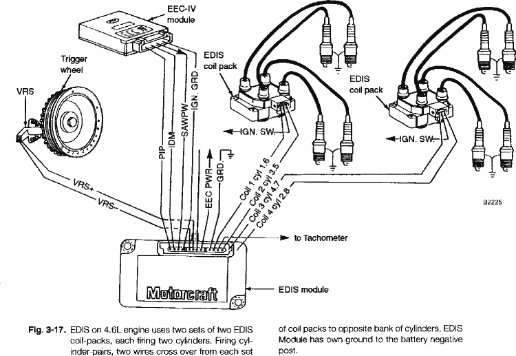
SAW Pulsewidth (usec) = 1536 - (25.6 x (desired spark advance in degrees)) Example: You want 29 degrees of advance. PW = 1536 - (25.6 * 29) PW = 1536 - (742.4) PW = 793.6 You would send a pulse that is 793.6 microseconds long to the EDIS module. The EDIS module will do all the work of timing the spark, you just send the advance pulse. The EDIS has an advance range of 57.4 degrees BTDC to 10 degrees ATDC. These correspond to the SAW widths of 64 and 1792 microseconds respectively. Physical installation On 4 cylinder engines pins 10 and 12 are used for the 2 coils. On 6 cylinder engines pins 10, 11, and 12 are used for the 3 coils. On 8 cylinder engines pins 8, 9, 11, and 12 are used for the 4 coils. On all engines the complementary coils are connected to the cylinders that are 180 degrees apart in the firing order. Example: Ford firing order for HO 5.0L and 351 engines is 1-3-7-2-6-5-4-8. You would connect cylinders 1 and 6 to the same coil, 3 and 5, 7 and 4, and 2 and 8. Follow the same approach on 6 and 4 cylinder engines. Diagram of the EDIS system Here is the pinout of the EDIS control module. The signal names
correspond to the diagram above.
4 cylinder EDIS module pinout
6 Cylinder EDIS module pinout
8 Cylinder EDIS module pinout
OEM EDIS module applications
If you know any of this information to be incorrect, please email me at pedward (at) dainst.com. |